Introduction
This is a well established and extremely versatile method of welding on tanks. Submerged-arc welding (SAW) involves the formation of an arc between a continuously fed electrode and the workpiece.
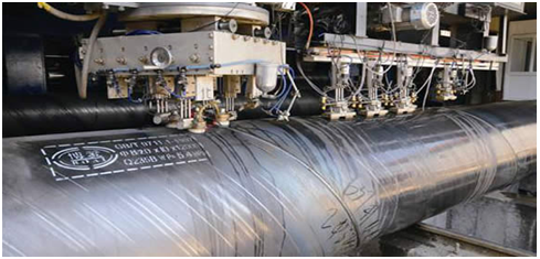
Similar to MIG welding, SAW involves the formation of an arc between a continuously-fed bare wire electrode and the workpiece. The process uses a flux to generate protective gases and slag and to add alloying elements to the weld pool. A shielding gas is not required. Prior to welding, a thin layer of flux powder is placed on the workpiece surface. The arc moves along the joint line and as it does so, excess flux is recycled via a hopper. Remaining fused slag layers can be easily removed after welding. As the arc is completely covered by the flux layer, heat loss is extremely low. This produces a thermal efficiency as high as 60% (compared with 25% for manual metal arc). There is no visible arc light, welding is spatter-free and there is no need for fume extraction.
Process Variants
According to material thickness, joint type and size of the component, varying the following can increase the deposition rate and improve bead shape.
Wire
SAW is normally operated with a single wire on either AC or DC current. Common variants are:
- twin wire
- multiple wire (tandem or triple)
- single wire with hot or cold wire addition
- metal powder addition
- tubular wire
Flux
Fluxes used in SAW are granular fusible minerals containing oxides of manganese, silicon, titanium, aluminium, calcium, zirconium, magnesium and other compounds such as calcium fluoride. The the main types of flux for SAW are:
- Bonded fluxes- produced by drying the ingredients, then bonding them with a low melting point compound such as a sodium silicate. Most bonded fluxes contain metallic deoxidisers which help to prevent weld porosity. These fluxes are effective over rust and mill scale.
- Fused fluxes- produced by mixing the ingredients, then melting them in an electric furnace to form a chemically homogeneous product, cooled and ground to the required particle size. Smooth stable arcs, with welding currents up to 2000A and consistent weld metal properties, are the main attraction of these fluxes.
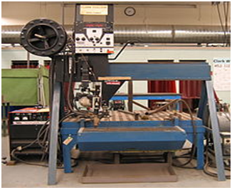
What Is SAW?
The SAW is usually operated as a fully-mechanized or automatic process, but it can be semi-automatic. Welding parameters: current, arc voltage and travel speed all affect bead shape, depth of penetration and chemical composition of the deposited weld metal.  Because the operator cannot see the weld pool, greater reliance must be placed on parameter settings.
The process is normally limited to the flat or horizontal-fillet welding positions (although horizontal groove position welds have been done with a special arrangement to support the flux).
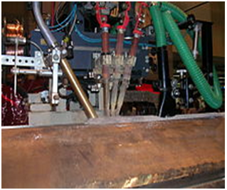
Single or multiple (2 to 5) electrode wire variations of the process exist. SAW strip-cladding utilizes a flat strip electrode (e.g. 60 mm wide x 0.5 mm thick). DC or AC power can be used, and combinations of DC and AC are common on multiple electrode systems.
Welding Operation
The flux starts depositing on the joint to be welded. Since the flux when cold is non-conductor of electricity, the arc may be struck either by touching the electrode with the workpiece or by placing steel wool between electrode and job before switching on the welding current or by using a high-frequency unit.
In all cases, the arc is struck under a cover of flux. Flux otherwise is an insulator but once it melts due to the heat of the arc, it becomes highly conductive and hence the current flow is maintained between the electrode and the workpiece through the molten flux.
The arc length is kept constant by using the principle of a self-adjusting arc. If the arc length decreases, arc voltage will increase, arc current and therefore burn-off rate will increase thereby causing the arc to lengthen. The reverse occurs if the arc length increases more than the normal.
A backing plate of steel or copper may be used to control penetration and to support large amounts of molten metal associated with the process.
Equipment of SAW Process

- Welding head
- Flux hopper
- Flux
- Electrode
Key SAW process variables
- Wire feed speed (main factor in welding current control)
- Arc voltage
- Travel speed
- Electrode stick-out (ESO) or contact tip to work (CTTW)
- Polarity and current type (AC or DC) and variable balance AC current